|
| |
Thai
English
Cable
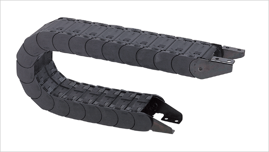
Drag Chains

| |
 |
| MAJOR USE : Applied to Machine tool,
industrial machine, all kinds of plant works, motor industry,
assembled machine and robot, etc. |
| ■ G. FLEX |
SHINSUNG SKC is installed for machine
manufacturing, plant works, motor industry, assembly machine,
robot and other field done with openable crossbar(bolt), it is
fully clsed up, so it protects connected electric wire, from
becoming dirty and popplued, as in the past.
Openble crossbar helps electric wire to be easily inserted
electric wires be in-stalled without disjointing,
Electric wire protective Conduit, G.Flex can be installed to the
direction that horizontal dir ection and horizon & ver-tical
are combined.
With respect to movable distance, preliminary knowledge on
structure in case of installing is almost not necessary. |
| special features |
- To protect connected electric wire from being polluted.
- To protect electric wire from being easily damaged,
- With Ablage to protect crossbar, the life span of E/W is
high,
- Good appearance,
- High stability
- Easy to control
- Stable against corrosion and chemicals,
- Simple installing-connected with nut,
|
Materials of duct parts
Ks-P strengthens glass fibre, and standard color basic is black.
Allowable scope of temperature
-10~+80
Allowable speed of transportation
120.m/min when arranged without support 80m/min when arranged
with support |
|
|
| Following instructions(matters) are required,
to supply technique fully. |
- To connect, pcs of E/W and outer dia to come next.
- All cable E/W and weight of Conduit including contents of
Conduit
- Minimum allowable curvature of radius of E/W. (by
order-giver's instruction)
- Movable distance
- Speed of transportation
- Max. acceleration delay
- Frequent moving
- Wide installing at option
- Tranformation of equipment/transformation of connection
equipment chart
- influence of circumerence(temperature,air humidity,etc)
|
| Structure |
| This constituted with Five parts such as ARM, Link(A),
Link(B), Stay, Divider. It can easily assembled without separate
tool. ARM can be easily opened in the indicated plade with a
driver using the principle of lever. |
| |
| Outer crossbar of open able arm connection |
|
|
| Divider used for separation(decomposi-tion) of E/W can be
movable. or can be fixed or assembled by simple replacing. |
| ■ Duct Connection |
|
|
For vertex connection, it should be done in the center of
move-route.
By arranging such way, the vertex and moving transfer distance
are conned-ed to the shortest, so the length of duct and length
of E/W also becomes the most economical.
Connection can be done by connection coupling made with thin
steel plate.
in coupling, the edge is pressed into the hole of side-joining
plate with outer blot, and in the vertex,it is pushed in the
part of hole. |
| ■ Connected transformation |
| Connected type desired can be directed when order is placed |
|
|
| ■ How to indicate when ordered. |
- please fill out the following items.
|
| 그림 |
| ■ TYPE SKC |
|
|
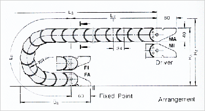
Explanation of concept:
BES=Width of duct
HES=Height of jointed plate
hi=Height from wall to wall
D=Diameter of straight line
KR=Radius of curvature
tES=Duct dividing
W=Length when it is not supported
LS=Distance of transfer
Be sure to preserve change of technipue
Length when it is not supported depends on added weight |
|
Type
|
radius of Curvature
|
duct size
|
weight in kg/m
|
|
t ES
|
hES
|
hi
|
d max
|
BES
|
W
|
|
SKC 340
|
70
|
34
|
40
|
25
|
22
|
70
|
50
|
1.5
|
|
100
|
|
150
|
150
|
130
|
2.1
|
|
SKC 470
|
100
|
47
|
55
|
36
|
32
|
106
|
80
|
2.5
|
|
150
|
|
200
|
186
|
160
|
3.5
|
|
250
|
|
SKC 640
|
135
|
64
|
75
|
50
|
44
|
140
|
110
|
4.0
|
|
200
|
|
250
|
250
|
220
|
5.0
|
|
300
|
|
SKC 850
|
180
|
85
|
100
|
68
|
30
|
186
|
150
|
5.7
|
|
250
|
236
|
200
|
6.5
|
|
35
|
336
|
300
|
8.0
|
8principle to install cable Duct
● Be sure to check if single cross section for connected
E/W is enough or not.
●100% of duct cross section shouled be existed asvacant
space.
● if cross sectio of E/W protective duct is not enough in
connection E/W, cable and duct should be dismantled totally.
● Be sure to confirm if the of curvature allowed by E/W
a-cording to order-giver's instruction is smaller than radius of
curved line of same as it.
●Please inspet if duct loading by loading chart of duct is
within per-mitted elicacy. |
|
| |

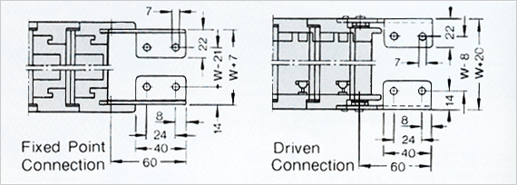
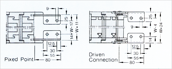
Connected transformation(body):
Coupling connecting MA
=Outside nut fixing side(standard)
Coupling connecting MI
=Inside nut fixing side(standard)
Vertex connection F1
=inside nut fixing side |
 |
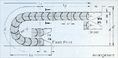
| Forming dimension changed depends on radius of bending |
Explanation of concept:
LB=Length of bending Line
UB=Projucting part
HA=Height ofconnection
HZ=Height of extra path required |
|
KR
|
LB
|
UB
|
HA
|
HZ min
|
|
70
|
356
|
218
|
210
|
280
|
|
100
|
450
|
248
|
270
|
340
|
|
150
|
607
|
298
|
370
|
440
|
| Cable Duct Length : |
 |
Becomes round at 34mm part |
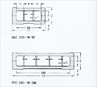
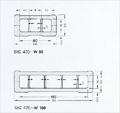
| ■ Duct-Cross section |
Electric Wire=파이 dmx=22mm
ao min=20mmD
Divider inside the width, it is fixed to height of 5mm or is
arranged in a mov ablestate without layer by replacing. Nos of
di-vider cross section can be instructed upon or dering. Divider
is installed generally each 4th duct piece part. |
 |
| ■ Connecting Measurement |
 |
| Type of conncetion desired can be in-structed upon or dering. |
|
| |

Connected transformation(body):
Coupling connecting MA
=Outside nut fixing side(standard)
Coupling connecting MI
=Inside nut fixing side(standard)
Vertex connection F1
=inside nut fixing side |
 |
| Forming dimension changed depends on radius of bending |
Explanation of concept:
LB=Length of bending Line
UB=Projucting part
HA=Height ofconnection
HZ=Height of extra path required |
|
KR
|
LB
|
UB
|
HA
|
HZ min
|
|
100
|
502
|
302
|
285
|
355
|
|
150
|
660
|
352
|
385
|
455
|
|
200
|
816
|
402
|
485
|
555
|
|
250
|
973
|
452
|
585
|
655
|
| Cable Duct Length : |
 |
Duct Pitch is based on 47mm |
| ■ Duct-Cross section |
Electric Wire=파이 dmx=32mm
ao min=22.5mm
Divider inside the width, it is fixed to height of 5mm or is
arranged in a mov ablestate without layer by replacing. Nos of
di-vider cross section can be instructed upon or dering. Divider
is installed generally each 4th duct piece part. |
 |
| ■ Connecting Measurement |
 |
| Type of conncetion desired can be in-structed upon or dering. |
|
| |

Connected transformation(body):
Coupling connecting MA=Outside nut fixing side(standard)
Coupling connecting MI=Inside nut fixing side(standard)
Vertex connection F1=inside nut fixing side |
 |
| Forming dimension changed depends on radius of bending |
Explanation of concept:
LB=Length of bending Line
UB=Projecting part
HA=Height ofconnection
HZ=Height of extra path required |
|
KR
|
LB
|
UB
|
HA
|
HZ min
|
|
135
|
680
|
413
|
378
|
448
|
|
200
|
885
|
478
|
508
|
578
|
|
250
|
1042
|
528
|
608
|
678
|
|
300
|
1200
|
578
|
708
|
778
|
| Cable Duct Length : |
 |
Duct Pitch is based on 64mm |
| ■ Duct-Cross section |
Electric Wire=파이 dmx=47mm
ao min=30mm
Divider inside the width, it is fixed to height of 5mm or is
arranged in a mov ablestate without layer by replacing. Nos of
di-vider cross section can be instructed upon or dering. Divider
is installed generally each 4th duct piece part. |
 |
| ■ Connecting Measurement |
 |
| Type of conncetion desired can be in-structed upon or dering. |
|
| |

Connected transformation(body):
Coupling connecting MA=Outside nut fixing side(standard)
Coupling connecting MI=Inside nut fixing side(standard)
Vertex connection F1=inside nut fixing side |
 |
| Forming dimension changed depends on radius of bending |
Explanation of concept:
LB=Length of bending Line
UB=Projecting part
HA=Height ofconnection
HZ=Height of extra path required |
|
KR
|
LB
|
UB
|
HA
|
HZ min
|
|
180
|
906
|
542
|
495
|
565
|
|
250
|
1126
|
612
|
635
|
705
|
|
350
|
1126
|
612
|
635
|
705
|
| Cable Duct Length : |
 |
Duct Pitch is based on 85mm |
| ■ Duct-Cross section |
Electric Wire-Ø dmax=64mm
a0 min=44mm
Divider inside the width, it is fixed to height of 5mm or is
arranged in a movable state with out layer by replacing. Nos of
divider cross section can be instructed upon or dering. Divider
is installed genetally each 4th duct piece part.`
|
 |
| ■ Connecting Measurement |
 |
| Type of conncetion desired can be in-structed upon or dering. |
|
|