|
| |
Thai
English

| |
 |
| ■ THE TELESCOPE COVER |
The use of the telescope cover has become very important in
coping with the rapid increase in technology and automation of
the machine tool industry in recent years.
The rapid develoment requires such things as rational business
practices, expanded productivity,and good factory, management.
SHINSUNG has for a long time been cooperating with various
machine tool makers to improve our products. The telescope cover
is a result of this. This telescope has, with the use of
advanced technoloty, been producted to conform to many types of
machines. Below is detailed explanation of the telescope cover.
1. SPECIAL FEATURES : We will produce to fit any machine.
2. APPROVED SPEED : We produce on the premise of 10m to 12m. If
you need to go over this, we ----------------------
will consult with you directly.
3.MATERIALS : We produce in both iron and stainless steel.
4.FINISHED SURFACE : Buff, black finish and zinc plating |
| ■ Below are the different
shapes of the telescope cover. |
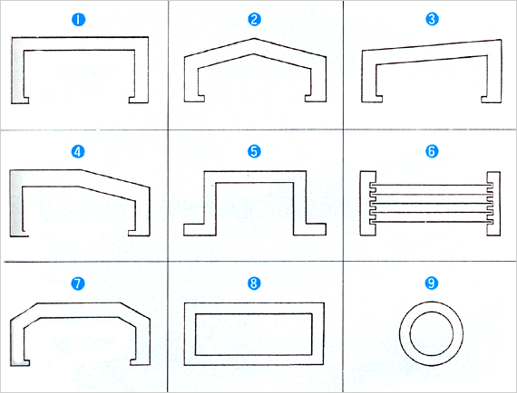 |
| We can produve shapes outside of these, so
please consult with us. |
| ■ Struction |
- COVER BOX
We use special kind of steel plate for the cover box. There
are 4 standards for the plate : 12mm,1.6mm,2.3mm and 3.2mm.
The thickness is decided based on the cover measurements and
the necessary intensity.
- WIPER
This' special wiper is used on the cover but it can also be
used on the side according to the design. (made of
polyurethane) The heat resistance of the wiper is the
standard 40 degree to 100 degree celsius.
It is also durable enough to protect against water and oil.
We can also make the telescope cover without wipers.
- WIPER COVER
We can istall a steel cover on the wiper in case you need to
protect the wiper from high temperatur insustiral dust.
- ROLL UP STRUCTURE
In principle, both ends of the cover roll up. this is the so
called box of each of the covers can match perfectly. This
can also put tension on the wiper accurately. Of course, we
can design a cover which goes up step by step. In order to
avoid the cover itself Lifting up, each wiper should be
suppressed by adequate tension.
|
|
| |
| ■ Characterisics : |
Possible to manufacture any shape
Material quality is simple to any use.
Anti-stagnant, anti-abrasion and dur ability are execllent.
Transporting fee is small due to light weight, so this economic. |
| |
| ■ Type of square-shaped Bellows |
| Any type outside of the above can be manufactured,
so contact us for negotiation! |
| ■ Major material quality |
As material used for body of square-shaped bellow, there is
NTP Sheet.
NTP is the best sheet with excelleent intensity, including
heat-resisting oil-resistings, wealther-resisting, anti-abrasion
and crookedness as mechanical material of Bellows. Special
care/attention should be given to similar type on appearance,
and it is necessary to bear in mind that the difference of value
is big.
Indifference for material quality would drop the quality of
product. |
| ■ Test Analysis of NTP SHEET |
|
Heat - resisting Test
|
Bending Test
|
Oil-resisting Test |
|
Machine..........................Lathe
Cuttings..............Bar
stell(SS41)
CHP Moment temperature 700 C
Distance ........................160mm
Time ..............................120sec
|
Testing M/C Bending Testing M/C
Bending degree ...................180
C
Frequency of bending 80,000 times
Time#DADAED1year
|
To dissolve ASTM No.! in
container for testing and put SHEET, and conduct deposition of
48 hourse. |
|
Nothing abnormal
|
Nothing abnormal
|
Nothing abnormal
|
Structure :
1.Bellows body is used. The thickness of Sheet is respectibely
0.6mm, 0.7mm, 0.9mm, and 1.2mm as standard ones, and for
selection of SHEET, it is decided by bellows width, pitch
standard and required intensity. |
2. END PLATE
Steel plate is used and thickness of steel plate is 1.2mm,
1.6mm, 2,3mm and 3,2mm as stand types.
3. Intermediate Support Plate(Slide Plate)
Using steel plate, strong vinyl chloride and veneer board, and
keeping the body of Bellows from touchint directly the SLIDE
PLATE to Bellows number 7-10.
4. ROLLER
ROLLER is fixed to SLIDE part so that Bellow can reciprocate
smoothly.
Maninly Nylon resin is used as material The shape can be
changeable according to type in addition to the picture seen.
5. SLIDE SHOE
In small and middle-typed BELLOWS, SLIDE SHOE consisted of
brass(BSP) or synthetic resin is used instead of ROLLER.
6. SEAT PLATE
Lt functions as connecting BELLOWS body to intermediate support
plate.
7.CNAIN TOOL
Please refer to th follow item.
8.BRACKET
When BELLOWS is shrinked, like the picture, BRACKET is set, if
there is no space on SLIDE surface of machine tool. This time it
is important to establish that connecting point between SLIDE
surface and BRACKET would not restrict the reciprocation of
BELLOWS. |
|
|
| ■ Chain Tool |
| This is mainly installed to which stroke of bellow is long or
to which bellows width is board , helping bellow have smooth
reciprocation |
 |
| 2. PANTGRAPH method(applied to machine with speed under
6m/sec) |
 |
This method is not limited to BED purpose of horizontal use.
and it is also installed to CLOWW RASIL use upon necessary.
3. Other method
There are BELT method, Limited TAPE method, etc. |
| ■ Outline design Standard of BELLOWS |
1. How to decide PITCH of BELLOWS
Considering SPACE to install such as Roller and TOGGLE PLATE,
etc. in limited measurement of H3, W3 W4 in the picture or
PANTOGRAPH, etc, the remained SPACE becomes PITCH of BELLOWS,
provieded, however, that you should avoid SPACE occupied by
Wiper, such case where there is Wiper at both sides of
table.Please pay attention to this point. |
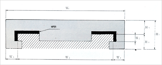 |
2. BELLOWS width and pitch
If we refer to P brank of the attched table after Pitch of
Bellow is decided, there is L. MIN standard for necessary
STROKE. |
|
Height to Mt. from gully
|
Open Pich between
Mt and Mt
|
Bellows width
W1
|
Width of SLIDE
surface W2
|
Standard when it is shrinked at the
least
|
|
Extended contractec speed under 10m mir
|
Extended &contractec speed under 10m mir
|
|
15
|
15~18
|
200
|
W1-50
|
|
|
|
20
|
20~24
|
300
|
W1-60
|
1/3ST
|
|
|
25
|
25~30
|
|
W1-70
|
1/4ST
|
|
|
30
|
30~36
|
500
|
W1-90
|
1/4.5ST
|
|
|
35
|
35~42
|
600
|
W1-100
|
1/5.5ST
|
|
|
40
|
40~48
|
800
|
(100)
W1-150
|
1/6.5ST
|
1/4.3
|
|
45
|
45~54
|
1000
|
(120)
W1-160
|
1/7.5ST
|
1/5.3
|
|
50
|
50~60
|
1200
|
(130)
W1-170
|
1/8.3ST
|
1/6.3
|
|
55
|
55~66
|
1400
|
(140)
W1-180
|
1/9.3ST
|
1/7.3
|
|
60
|
60~72
|
1600
|
(150)
W1-190
|
1/10.3ST
|
1/8.3
|
|
65
|
65~78
|
1800
|
(160)
W1-200
|
1/11.3ST
|
1/9.3
|
|
70
|
77~84
|
2000
|
(170)
W1-210
|
1/12.3ST
|
1/10.3
|
 |
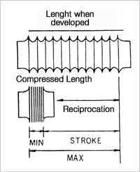
3.L.max(Developed length of Bellows)
Like the picture L.MAX of Bellows becomes L.MIN of
STROKE+BELLOWS of TABLE,
As for L.MAX, please think of Open Pitch=Mt. number. This time,
L.MIN is important element alon with L.MAX for Bellows. It may
be proper to catch L.MIN as the least, if possible , there is al
limit by pitch of bellow. Such case where SPACE of L.MIN is
limited, L.MIN of Bellows can be reduced if we re-duce Mt number
while making pitch bigger.
L.MIN of Bellows has a small difference according to PITCH,but
you may take it as about 60mm of 10Mt. |
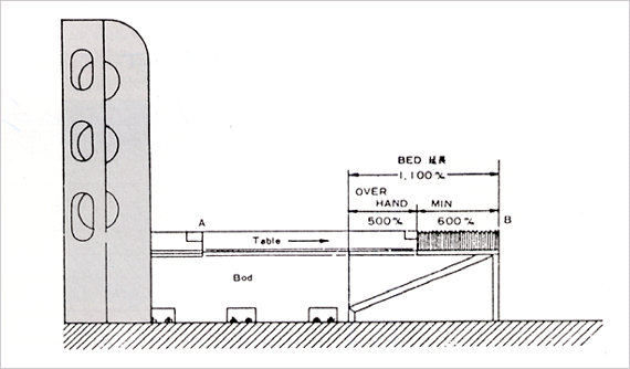
4. Example of Take-up
① When MIN of Bellows(length when shrinked) is 600m/m,
BELLOWS is taken up, and 600m/m=1, 100m/m, that is , BED
extension of 1,100m/m should be done.
②Take-up plate of BELLOWS taken up to A part and B part
Bellows body should be fully made horizon with SLIDE surface of
BED, you should be mindful of this. |
 |
| 그림 |
| ■ BFD Dimension |
| |
M A X |
|
브라켓트 (요.불요) |
| |
스트로크 |
|
|
| |
와이퍼두께 |
|
|
| |
최소로오므렸을때 |
|
|
|
| ■ How to order |
| BELLOWS형식 |
형 |
(카다로그를
참조해
주십시오.) |
|
|
| |

■ Cylinder-type BELLOWS
Shape |
 |
| ■ Major Materials |
Nylon Tarpaulin is mainly used to cylinder-type BELLOWS, as
coating and processing vynil chloride resin to both sides of
Nylon fiber.
With respect to water-resisting degree, tension-resisting
tensile elasticity, tensile strength, it is excellent, while the
heat-resisting is about 60c, and such case where BELLOWS
requires of heat-resisting, separately NTP sheet is useed. |
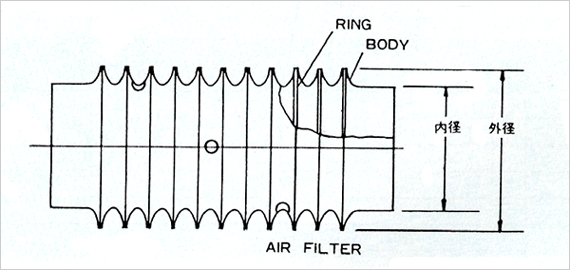
| ■ Structure |
Constituted with Nylon Tarpaulin and steel line(SWP).
By using tension-resisting of Tarpaulin, steel line, RING is
inserted for manufacturing, and the line diameter of RING
becomes thicker, as the outer diameter of BELLOWS becomes
larger, Avilable scop of manufacturing. |
 |
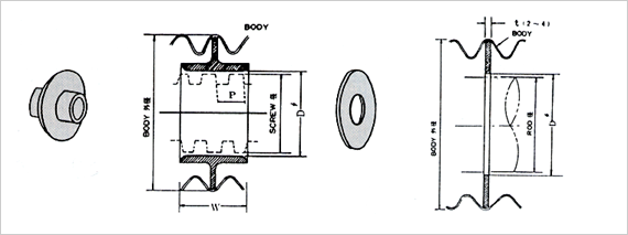
| ■ Shupportilng Stuctureials |
| If cylinde-type BELLOWS grows longer or operated by being
installed horizontally, the midway part of BELOOWS hands down,
so in order to help smooth operation of BELLOWS, supporting
structure like the picture (made from PVC plate and PVC pipe or
gun metal) is installed at each proper interval. |
 |
| ■ Calculation standard of dimension |
 |
|
MAX required by
Belows
|
PITCH agreeable with outside with outside diameter of
Bellows
|
= Nos of Mt |
| |
|
|
|
| |
|
|
| MAX = MIN+STROKE |
| MIN = Pitch x thickness of pitch |
|
1.Making the insice diameter of Bellows as
standard, the inside diameter of BELLOWS is decided giving
consideration to CLEARANCE of 8mm rather than SHAFT(ROD)
diameter, and outside diameter of BELLOWS is decided as bigger
than the inside diameter according to chart.
2.Making set-caliber as standard,However, when limited by length
of shrinkage(MIN), it becomes bigger that chart PIT(as outside
diameter of BELLOWS becomes bigger), and this time, wrinkles
happens at gully part of C, somewhat appearance of product is
bad, but there is no trouble in using. |
| ■ Bellows Dimension Standard table |
|
BELLOWS
Inside diameter
|
BELLOWS
Outside diameter
|
PITCH
|
Thickness of me
|
|
40
|
60
|
9
|
≒ 2.6mm
|
|
80
|
100
|
12
|
|
120
|
145
|
15
|
|
145
|
175
|
18
|
≒ 2.8mm
|
|
190
|
230
|
24
|
≒ 3.2mm
|
|
235
|
280
|
27
|
|
290
|
340
|
30
|
≒ 3.9mm
|
|
380
|
440
|
36
|
|
480
|
550
|
42
|
≒ 4.4mm
|
| ■ Open-type Bellows |
| By opening and closing the open-part with FASTNER or MAGIC
Tape like picture, not disssolving the already assembled
machine, it can easily install BELLOWS, However, be mindful of
BELLOWS outside diameter growing bigger compared to general
BELLOWS.(and MIN) |
| ■ How to Instal |
| Both section of cylinder-type BELLOWS can be installed with
FLANGE of BAND like picture bellow. |
| ■ Matters clarified when ordering |
1. L.MIN 2. STROKE 3. SHAFT or ROD diameter
4. Condition of use(heat-resisting, oil-resisting pressure)
5. Position of use(Horizon, vertical, others)
6. Speed of reciprocation
7. Diameter of the part taken up.(inside&outside diameter of
FLANGE when it is FLANGE) |
|
|
